Understanding the Centre of Buoyancy and Its Relationship with Draft
The centre of buoyancy is one of the most fundamental concepts in naval architecture, yet its behaviour is often misunderstood by those new to the field. This single point governs how a vessel floats, how it responds to loading changes, and ultimately how it maintains stability at sea. Understanding its position and movement is essential for anyone involved in ship design or operation.
What is the Centre of Buoyancy ?
The centre of buoyancy, denoted as ‘B’, is the geometric centroid of the underwater volume of a floating vessel. In simpler terms, it is the centre point of all the water the ship pushes aside to stay afloat.
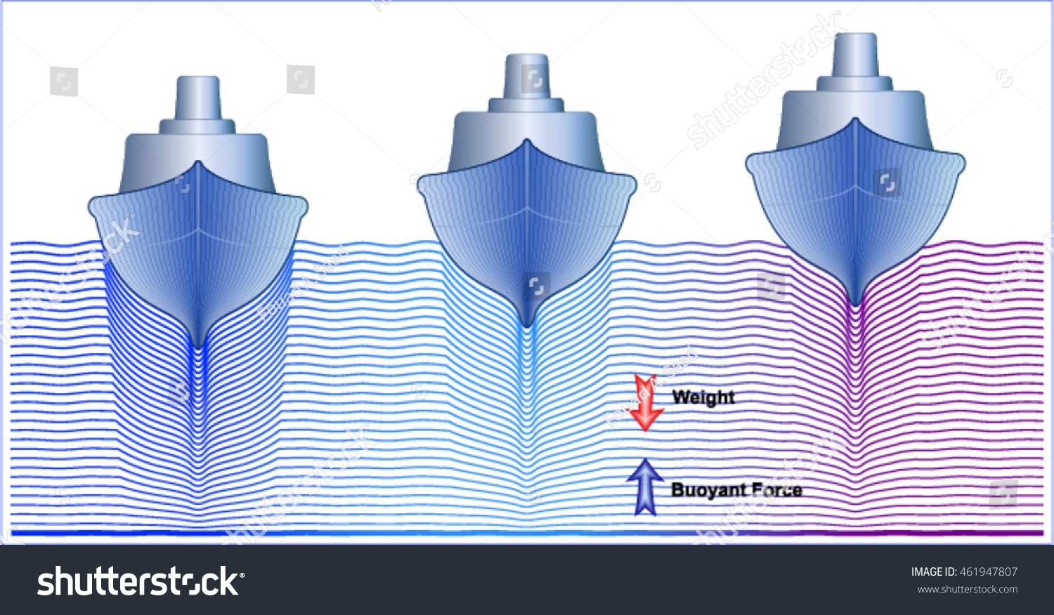
When a ship floats, it displaces a volume of water equal to its own weight divided by the water density. This displaced water exerts an upward buoyant force on the hull. While this force acts across the entire wetted surface, we can represent it as a single vertical force acting through one specific point. That point is the centre of buoyancy.
The concept mirrors how we treat the weight of a ship. A vessel contains thousands of tonnes of steel, machinery, cargo, and consumables distributed throughout its structure. Rather than calculating forces from each individual item, we represent the total weight as a single downward force acting through the centre of gravity. Similarly, the distributed pressure forces from displaced water are represented as a single upward force through the centre of buoyancy.
For a vessel floating in static equilibrium, the centre of buoyancy and centre of gravity must lie on the same vertical line. If they are offset horizontally, the vessel will heel until they align.
Defining the Position of Centre of Buoyancy
The position of B is expressed using three coordinates relative to the ship’s reference system. The longitudinal position is measured from the aft perpendicular or midships, typically called the Longitudinal Centre of Buoyancy (LCB). The transverse position is measured from the centreline, called the Transverse Centre of Buoyancy (TCB). The vertical position is measured from the keel or baseline, called the Vertical Centre of Buoyancy (VCB) or simply KB.
For a symmetrical vessel floating upright, the TCB lies on the centreline. Any deviation indicates the vessel is heeled to one side. Naval architects focus primarily on LCB and VCB during design and loading calculations.
The position of B depends entirely on the shape of the underwater hull. It is calculated by integrating the underwater volume and finding its geometric centre:
KB = ∫ z dV / V
Where z is the vertical distance from the keel, dV is an element of underwater volume, and V is the total displaced volume.
Similarly, LCB is calculated by integrating the longitudinal moment of the underwater volume and dividing by total volume.
How Centre of Buoyancy Changes with Draft
As a vessel’s draft increases, the underwater volume grows and its shape changes. Consequently, the centre of buoyancy shifts position. Understanding this movement is crucial for predicting vessel behaviour during loading operations.
Vertical Movement of B with Increasing Draft
When draft increases, the vertical centre of buoyancy (KB) rises. This occurs because additional underwater volume is added above the previous waterline. The centroid of the total underwater volume shifts upward to account for this new volume.
Consider a simple rectangular barge as an example. If the barge has a constant beam and length at all drafts, the underwater volume is a rectangular box. The centre of buoyancy lies exactly at half the draft:
KB = T / 2
Where T is the draft. As draft increases from 2 metres to 4 metres, KB rises from 1 metre to 2 metres above the keel.
Actual ship hulls are more complex. The bottom is often relatively flat while the sides may have flare or tumblehome. The relationship between KB and draft follows a curve rather than a straight line. For conventional hull forms, KB typically ranges from 0.51T to 0.54T for full-bodied vessels like tankers and from 0.48T to 0.52T for finer vessels like container ships.
Naval architects calculate KB values across the full range of operating drafts and present them in hydrostatic tables or curves. These values are essential for stability calculations at any loading condition.
Longitudinal Movement of B with Changing Draft
The longitudinal centre of buoyancy (LCB) also shifts as draft changes, though the direction depends on hull form characteristics.
Most commercial vessels have fuller hull forms forward and finer forms aft at lower drafts, with this difference diminishing as draft increases. As the vessel settles deeper, the underwater volume becomes more symmetrical about midships.
For a typical cargo vessel, LCB might be located 2 percent of length aft of midships at light draft and shift to 1 percent aft of midships at full load draft. This forward movement occurs because the additional volume from increased draft is distributed more evenly along the length.
The opposite can occur for vessels with significant stern sections like cruise ships or vessels with large engine rooms aft. As draft increases, the relatively full stern contributes more volume, potentially shifting LCB aft.
Understanding LCB movement is essential for trim calculations. When loading cargo, the longitudinal centre of gravity changes. The vessel trims until LCB aligns vertically with LCG. Knowing how LCB moves with draft allows accurate prediction of final trim.
Practical Example of Centre of Buoyancy Movement
Consider a bulk carrier with the following characteristics at two different loading conditions:
Light Ballast Condition: Draft: 6.0 metres Displacement: 25,000 tonnes KB: 3.2 metres above keel LCB: 1.5 metres aft of midships
Fully Loaded Condition: Draft: 14.0 metres Displacement: 85,000 tonnes KB: 7.4 metres above keel LCB: 0.8 metres aft of midships
As the vessel loads from ballast to full cargo, the draft increases by 8 metres. The centre of buoyancy rises by 4.2 metres, reflecting the additional underwater volume. Simultaneously, LCB shifts forward by 0.7 metres as the deeper hull form becomes more symmetrical.
These changes directly affect stability. The rising KB increases the distance between keel and centre of buoyancy, which generally improves stability by raising the metacentre. The shift in LCB must be matched by appropriate cargo distribution to achieve desired trim.
Centre of Buoyancy Movement During Heel
When a vessel heels, the underwater shape changes asymmetrically. One side submerges deeper while the other rises. The centre of buoyancy shifts toward the lower side because more volume exists there.
This transverse shift of B is fundamental to ship stability. When the vessel heels to starboard, B moves to starboard. The buoyant force now acts through a point offset from the centreline. If the centre of gravity remains on the centreline, a righting moment is created that pushes the vessel back upright.
The path traced by B as the vessel heels through various angles defines the vessel’s righting characteristics. Naval architects plot the vertical line through the shifted B for each heel angle. The intersection of this line with the centreline determines the metacentre position, which governs initial stability.
For small heel angles, the transverse movement of B is approximately proportional to the heel angle. The relationship between this movement and the resulting righting moment defines the metacentric height GM, the primary measure of initial stability.
Significance in Naval Architecture Practice
The centre of buoyancy position influences virtually every aspect of vessel design and operation.
During initial design, naval architects shape the hull to achieve desired LCB positions that balance resistance, seakeeping, and trim characteristics. A more forward LCB may improve resistance in some cases but can cause excessive bow-down trim when loaded.
During loading calculations, KB values from hydrostatic tables feed directly into stability assessments. The metacentric height calculation requires accurate KB:
GM = KB + BM – KG
Where BM is the metacentric radius and KG is the vertical centre of gravity. Errors in KB translate directly to errors in calculated stability.
During inclining experiments, the measured heel response to known weight movements allows calculation of actual KG. This requires accurate KB values from hydrostatics to determine the true centre of gravity position.
Conclusion
The centre of buoyancy represents the point through which all hydrostatic pressure forces effectively act on a floating vessel. Its position changes continuously with draft, heel, and trim as the underwater hull volume changes shape. Understanding how B moves—rising with increased draft, shifting longitudinally with changing hull fullness, and moving transversely during heel—provides the foundation for all stability analysis. For naval architects and ship operators alike, accurate knowledge of B position across all operating conditions is essential for safe and efficient vessel operation.